VOR, CVOR, DVOR, and VOR Frequency Range
The VOR is a radio navigation aid that operates in the VHF band and provides the pilot with the magnetic direction to or from the ground station.
Operating Principles
- Frequencies: Operates in the VHF band, between 108.00 MHz and 117.975 MHz.
- 108.00 - 111.95 MHz: Shared with ILS. VOR uses frequencies with an EVEN first decimal (e.g., 108.20, 108.45). ILS uses odd decimals.
- 112.00 - 117.975 MHz: Exclusive use for VOR.
- Signals: The station transmits two 30 Hz signals:
- Reference Signal: Omnidirectional (constant phase in all directions).
- Variable Signal: Directional (rotating). Its phase changes according to direction.
- Radial Determination: The receiver measures the phase difference between both signals. This difference in degrees corresponds to the magnetic radial the aircraft is on.
- Example: If the phase difference is 90°, the aircraft is on radial 090.
VOR Types
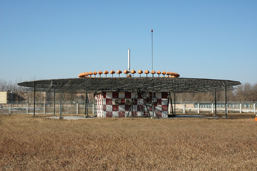
- CVOR (Conventional VOR):
- Reference Signal: Frequency Modulated (FM).
- Variable Signal: Amplitude Modulated (AM) by a physical rotating antenna.
- Susceptible to site errors (multipath).
- DVOR (Doppler VOR):
- Reference Signal: Amplitude Modulated (AM).
- Variable Signal: Frequency Modulated (FM) simulating rotation using an antenna ring (Doppler Effect).
- Advantage: Much more accurate and less susceptible to site/multipath errors thanks to the FM variable signal.
- TVOR (Terminal VOR): Low power, short range (25 NM), used at aerodromes.
- VOT (VOR Test Facility): Emits a test signal with zero phase difference (Radial 180 in all directions). Used on the ground to check equipment (Indication: 180 TO or 360 FROM with needle centered).
Instruments and Indications
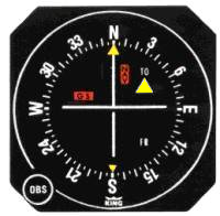
- CDI (Course Deviation Indicator):
- OBS (Omni Bearing Selector): Allows selecting the desired course.
- Deviation Needle: Shows angular deviation from the selected course.
- Scale: Typically 5 dots on each side. Full Scale Deflection = 10° (2° per dot).
- TO/FROM Indicator: Indicates if the selected course leads to (TO) or from (FROM) the station.
- TO: The selected radial is more than 90° from the current radial.
- FROM: The selected radial is less than 90° from the current radial.
- RMI (Radio Magnetic Indicator):
- Needle Tail: Indicates the current Radial (QDR).
- Needle Head: Indicates the magnetic heading to the station (QDM).
Range and Accuracy
- Range: Limited by Line-of-Sight.
- Approximate formula: $Distance (NM) = 1.23 \times \sqrt{Height (ft)}$.
- Accuracy: $\pm 5^\circ$ (on airways).
- Established: On approaches, considered established within half scale deflection (5°).
- Monitoring: The monitor shuts down the VOR or removes identification if the bearing error exceeds 1° or power drops by more than 15%.
Procedures and Additional Concepts
- Radials: Always magnetic and FROM the station. Magnetic variation at the VOR location is used.
- Cone of Confusion: Area above the station where no signal is received or it is erratic.
- Scalloping: Signal waviness caused by terrain reflections.
- ATIS: Some VORs transmit airport ATIS information on their frequency.
Enroute Navigation
