Instrument Landing System (ILS): Localizer and Glide Slope
The ILS (Instrument Landing System) is the standard precision approach system, providing lateral and vertical guidance for landing.
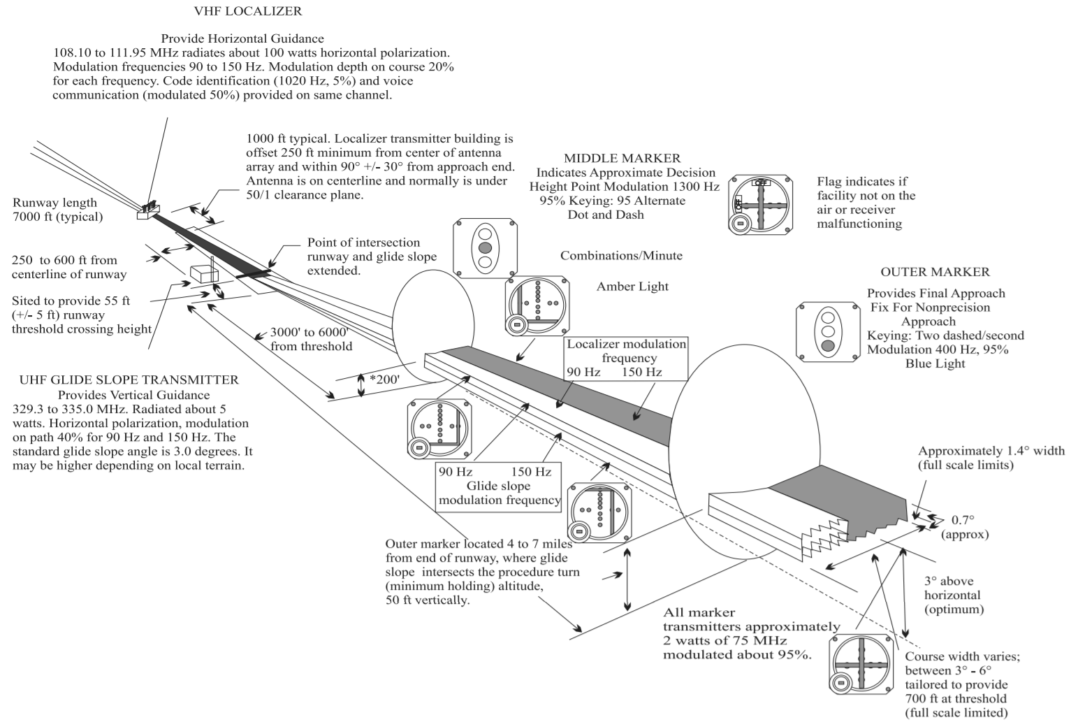
System Components
- Localizer (LOC): Provides lateral guidance. Operates in VHF (108.10 - 111.95 MHz, odd decimals only). Uses two lobes modulated at 90 Hz (left) and 150 Hz (right).
- Glide Path (GP): Provides vertical guidance. Operates in UHF (329.15 - 335.0 MHz), automatically paired with the LOC frequency. Uses lobes of 90 Hz (above) and 150 Hz (below). The standard angle is 3°.
- Marker Beacons: All operate at 75 MHz.
- Outer Marker (OM): Blue, dashes. Indicates the FAF.
- Middle Marker (MM): Amber, dot-dash. Near CAT I minimums (approx. 1 NM from threshold).
- Inner Marker (IM): White, dots. Near the threshold (CAT II/III).
Coverage and Accuracy
- Localizer: 25 NM within ±10° and 17 NM within ±35° of the centerline.
- Glide Path: 10 NM within ±8° of the centerline.
- Sensitivity: The ILS is much more sensitive than the VOR. A full-scale deflection on the LOC is 2.5° (compared to 10° for VOR).
Usage and Procedures

- Established: Considered established when deviation is less than half scale (1.25° on LOC, 0.35° on GP).
- Interception: Always intercept the glide path from below to avoid false glide paths (side lobes that appear at higher angles, such as 9°).
- Back Course (BC): Use of the localizer's back beam. On a normal CDI, indications are reversed, but on an HSI, correct indications can be obtained by setting the front course.
Operation Categories (Installation)
- Category I: Guidance down to 200 feet (DH).
- Category II: Guidance down to 100 feet (DH).
- Category III: Guidance down to the runway surface.
Critical and Sensitive Areas
- Critical Area: Zone where the presence of vehicles or aircraft causes unacceptable interference. Protected whenever the ILS is in use.
- Sensitive Area: Wider zone protected during low visibility operations (CAT II/III) to prevent beam fluctuations that the autopilot might erroneously follow.
Approach Charts
